Experimental Z Axis Gear Train
I was thinking about alternative ways of driving the second Z axis rod. Using two motors seems a bit redundant, and timing belts have to be the right size and can be tricky to source. This isn't much of a problem for most people wanting a 3D printer - but if you're experimenting with the technology then having something more 'reprapable' has it's advantages.
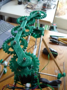
One way would be to use a gear train between the rods. This seemed like an interesting line to pursue, as it gave me an excuse to learn how to design gears, and what's the point of having a printer if you can't play a little. So, firing up Openscad and the excellent "Parametric Involute Bevel and Spur Gears" script from Greg Frost, I worked out how to build a set of gears to connect the rods on my test rig. I also put together a basic frame to hold them in place using Tinkercad (which coincidentally tested how big a part my Prusa can actually print).
Gear train mounted on top
Having the gears in this curve was not actually planned to be honest (my calculations were a little off), but it did show a way in which access to extruder could be possible if they were mounted on the top of the machine - assuming some sort of guard around the gear mechanism.
Testing showed immediately a clear problem with this approach - backlash. The poor tolerances between the gear teeth accumulates along the train resulting in a noticable delay between the start of the driver gear and the start of the final driven gear when the direction of movement is changed. This is nicely shown in the video.
There's a few things to note:
- The problem only occurs when changing direction which, on the Z axis, does not happen for the duration of a print except at the very start after the axis has gone to home.
- This could potentially be mitigated by going to home and then priming the gears by moving in the opposite direction for a very small distance. I imagine this would be difficult to do with precise.
- Another idea is to move the driving motor to the middle gear. This would mean that each end would turn at approximately the same time, but there would be still some play between the driving and driven gears.
- Increasing the tolerances of the gears would also reduce the backlash. However this depends on the quality of prints, and also how high a quality can be hoped for in printed plastic parts.
The backlash problem seems horribly obvious with hindsight. Perhaps I could have worked it out from a bit more thinking, or from a bit of googling or asking on the forums, but by being able to quickly build a prototype I got to learn about making gears and think more about the problem than I would from just reading about it. And maybe posting this will help others in some way. The joys of 3D printing!
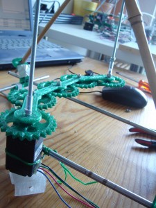
Gear train mounted underneath
Gear train mounted on top
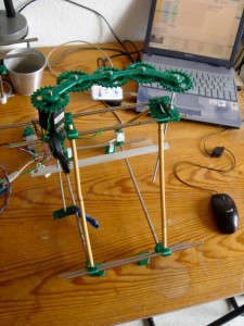
Alternate view from above
Comments
-
Dale Dunn
08-10-2011 03:41
Gary,
That's a fun and interesting idea. I like it.
One way to completely eliminate backlash that you didn't list is to use scissor gears. These are most commonly (I think) used in engine valve train systems to eliminate backlash. They're still efficient, and not much harder to build. You wouldn't have to tune the prints to perfection. They do require some springs, but I think a suitable printed spring shouldn't be too hard to come up with.
-
Gary Hodgson
08-10-2011 10:12
Hi Dale,
Thanks for the comment - it makes me realise that writing the post was worth it because I might not have come across scissor gears otherwise. After some more browsing I also found the following site which gives a good description (with diagrams) of how they work: http://www.brighthub.com/engineering/mechanical/articles/65169.aspx (I believe they are talking about the same thing).
If I get time I will have a go at printing some out and post the results. It would definitely be interesting if the springs could be printed too!
-
anon
08-10-2011 13:18
the backlash of gears system composed of identical wheals is b*(2^(n-1)) where b is the backlash between two gears and n is the number of gears.
This is very visible in toy cars plastic gear boxes.
So one way to reduce backlash is to reduce the number of gears: in your case put a 45 degrees beveled gear on the z rods and connect them with a row having two other 45 degrees gears and drive this rod directly with the stepper motor.
then improve the quality of your gears shape. but this has a limit as backlash is necessary in order to avoid the gear jamming.
Then increase the stiffness of your setup.
Then try to implement designs to compensate for the remaining backlash. like the scissor gears.
-
Dale Dunn
09-10-2011 14:16
There hasn't been a lot done in the RepRap community with printed springs, but there is precedent. I think the original Mendel design had printed springs under the print bed. I've used the elasticity of ABS in a spring-like component too. A spring doesn't have to be a coil, so I'm sure you could imagine something.
-
Martin Price
14-10-2011 12:50
Yes a horizontal rod with two bevel gears would be a better solution. In addition , the weight of the x carriage on the gears would reduce the backlash on a bevel to acceptable levels.
-
Rudi
20-03-2014 13:44
This is quite an interesting approach. Have you researched this further? If so, would you mind sharing your findings?
-
Thierry C.
09-07-2014 07:01
I worked on this solution since January 2013 but I hesitated to publish it since I had no opportunity to test it first on an already working Prusa 2 (my own one contains a similar mechanism built with scavenged and bought gears but I never dared to take it down since it works) and nobody else seemed interested or seriously motivated by this solution.
Nevertheless I recently mounted my kit on a Prusa 2 frame from a friend and it seems mechanically smooth after adjusting the gears' backlash.
An older version (gears' cages redesigned for easier mounting and crank added since) can be found on his website : but the mounting instructions are still missing. Just pay attention that the Z threaded rods need to be a bit longer since they are directly bound ot the bevel gears with no intermediate coupler.
Let me know if still interested and I'll publish the latest version with mounting instructions... and even the OpenSCAD (not ideally well written) source code.
-
Thierry C.
09-07-2014 07:04
Oops, HTML syntax error and impossibility to correct my post.
Two Z-axis motors are too much !
-
zhivko
26-09-2014 13:30
What is suggested backlash for 3d printed gears?


