Experimental Off-Carriage X-Axis
I recently had an idea about moving the X axis motor off the X carriage. I suspect there is little benefit of doing this, but I felt I had to at least knock out a quick prototype to see it in action.

The video below actually details it all quite well, but i'll also add a few pictures and a description below.
So, the idea is to move the X motor off the carriage. One immediate benefit is that the size of the entire X axis is no longer constrained by the size of the motor, perhaps leading to more compact designs? It would be interesting to try out a vertical X axis design with this setup.
Anyway, the X motion is transferred to the belt via a square extrusion rod which drives a cog which sits directly on it. This rod slides through the mount and cog during Z motion. The belt in this design is within the two X smooth rods, but other layouts could be adapted to move the belt to the outside (as with the original Huxley I believe). In this design the hot-end would either have to fit through the belts, or hang over the edge of the rods. Again, here the vertical layout would be interesting.
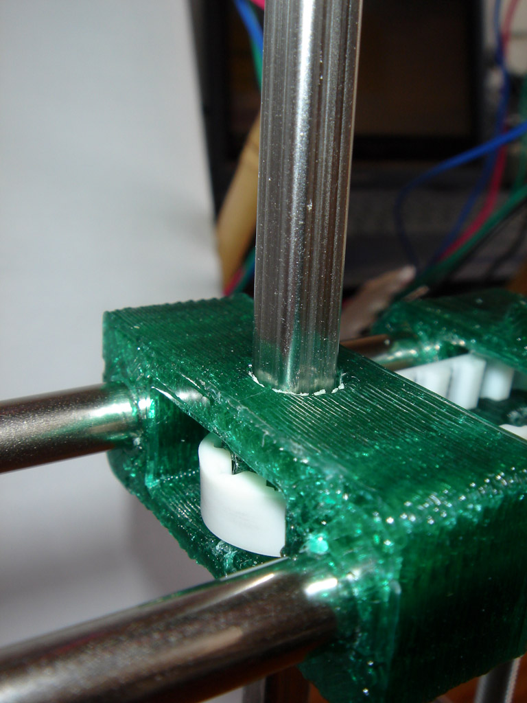
Detail of the drive cog mount

Detail of the idler
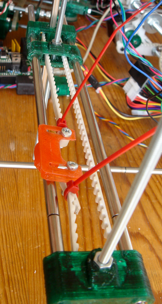
A temporary text X carriage
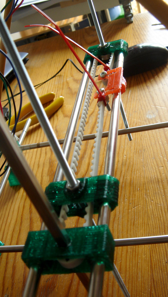
View from drive end
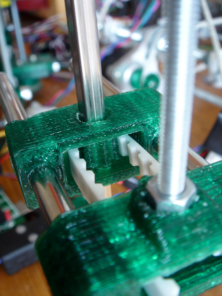
Detail of drive cog

The test rig - bamboo, duct tape and spare parts
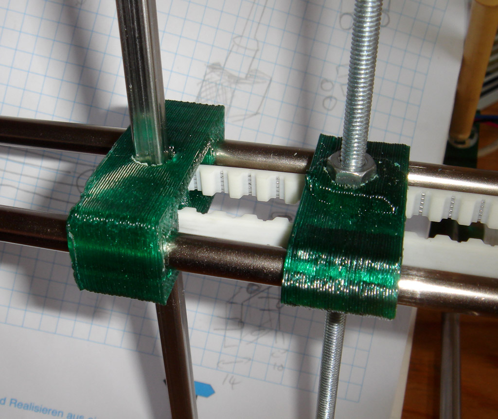
X Drive Cog Mount
The drive rod must be parallel to the Z rods
Comments
-
whosawhatsis?
27-09-2011 23:29
Very interesting! It might work better, though, on a machine with a Darwin-style X/Y axis, so that it could take weight off of a fast-moving axis instead of the slow-moving Z-axis. I'm designing a bot of this type and I'll add this to the list of mechanisms I'll consider to get the X motor off the Y axis.
OTOH, if you also used a bowden extruder to take the extruder motor weight off of the Z-axis, this should make that axis light enough to use a belt drive instead of leadscrews and make it just as fast as the other axes. Not sure why you'd need that since the Z axis only needs to move in small, infrequent steps during a build, but it would be a cool capability.