Prints from Vat #2
After waiting a couple of days for the silicone on vat #2 to dry I got around to testing it out. This version is identical to the first, but with a 4mm perspex bottom, and better care taken drilling the bolt holes. Initial tests seem successful, but it will take a few days/test cycles to see if the cracking problem occurs again.
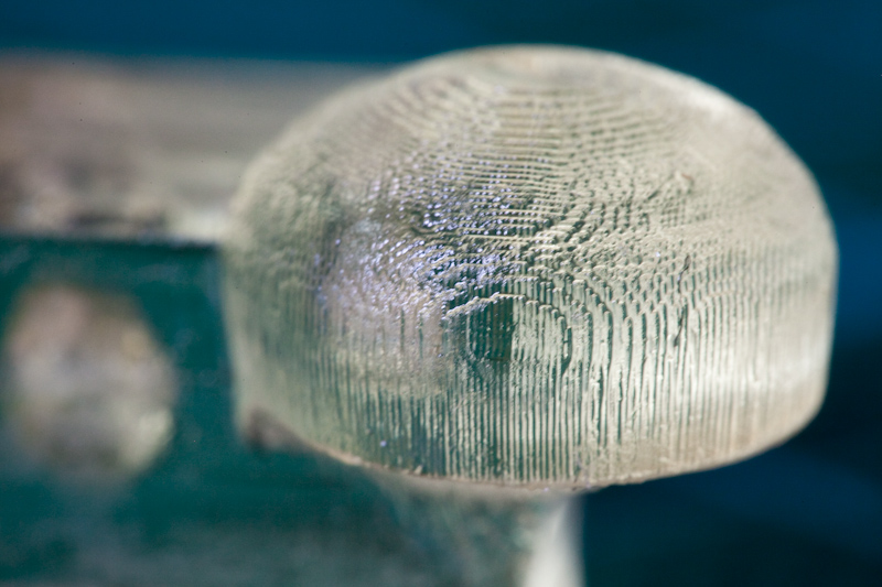
Another change I introduced to the exposure cycle was to move the Z axis up 3mm after each exposure, then moving it back 3mm minus the slice height. This was to ensure the last exposed layer was not sticking to the vat floor and causing deformation of the print, as I had hypothesised in the previous post. Looking at the cube-sphere test model here though the same problem occurs, therefore this hypothesis fails. The extra Z movement in the cycle is probably a good thing to have in any case, even though it adds a few seconds to each slice time.
Cube-Sphere Model
Cube-Sphere Closeup

Cube-Sphere
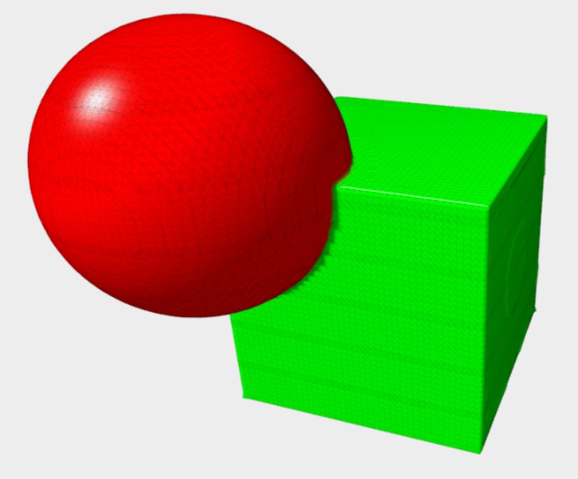
Cube-Sphere - Model
The Cube-Sphere is a simple model created from a Functional Representation CSG program I am working on (which needs its own post sometime). The same deformation occurred again as it did in round 1, and I now suspect it has more to do with newer layers bleeding into the older layers, and lack of support. It will prove to be a good test piece as I dial in the layer height vs. exposure time. I also plan on buying some pigment to help assert control, and look into creating support structures. It's worth mentioning that version 0.8.3 of Slic3r introduced experimental support material for SVG, but I have not yet had time to test it.
The image below highlights an interesting problem. I created the model so each part is hollow, but the way the print is pulled out of the resin - together with the amount of resin - caused some to be trapped. This is nicely shown below by the bubble, which would move around when the part was rotated showing that the contents were still fluid. It became solid after a few minutes under the post-cure lamps.

Cube-Sphere - Bubble
Assuming we desire the part to be completely hollow we now have an interesting challenge - how to "drain" the part before it is enclosed? As it happens, this was another reason I decided to abandon the powder printer. One of my long-term goals is to develop efficient fill algorithms, as I outlined in a previous post. If a part is to be printed in a powder bed, and the part is enclosed, then it follows that, unless some form of drainage is designed in the part, the loose powder will be encased.
There are a couple of solutions for the DLP printer that immediately come to mind. One could raise the part above the resin level completely, and when re-lowered the air trapped in the gap would push the resin aside, leaving the empty space. This assumes of course that the enclosed gap is complete, and air-tight. Another approach could be to reduce the resin level to be as low as possible. Ideally this would be exactly the slice height, but with such small tolerances I can imagine problems being introduced: surface tension; accumulated errors in the z axis; plus simply being able to position the feed mechanism so accurately would all cause headaches. So a minium acceptable tolerance would have to be accommodated. Still, that's a problem for sometime in the future.
Goldberg Polyhedron
Goldberg Polyhedron - Side

Goldberg Polyhedron - Top

Goldberg Polyhedron - Bottom
George Hart's model of Michael Goldberg's polyhedron has quickly become the "Hello World" of resin printers. I tried to print a half of the model simply because it was in my test folder, not expecting it to print at all. Surprisingly it came out reasonably well, except that the sides suffer from z-layer bleeding. Several of the holes remained filled with resin - some isopropyl alcohol and some diligent cleaning would sort that out I think. I should note that each square on the mat in the photos is 10mm across.

Failed Goldberg Polyhedron
Even the failed prints look good! Here the print failed to attach to the base and remained on the vat floor for the duration, leaving a 2D projection of the half-sphere.
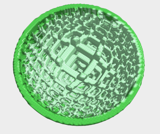
Microstructure Model
Microstructure Model - Bottom
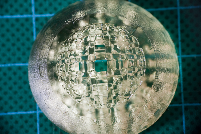
Microstructure Sphere - Partial - Top
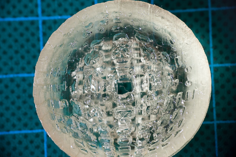
Microstructure Sphere - Partial - Bottom
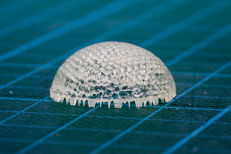
This model is again from the Functional Representation program. In my search for efficient fill algorithms I came across the work of Alexander Pasko and various colleagues, particularly a paper entitled "Procedural Function-based Spatial Microstructures" (PDF) which details exactly what I was looking for. Since then I have been attempting to recreate their findings, particularly the models with parametrised internal structure. Last week I finally was able to create the model and so of course it was one of the first things I wanted to print. The photo's do not really do it justice - and there is still a lot of improvements to make - but I was pretty excited to print some resemblence to the model. Below is an image from a later paper, "Procedural Function-based Modelling of Volumetric Microstructures" (PDF) which shows how the model should look. The first image in the gallery above is the model I created, and the photos are of a print of the middle quarter of the sphere, and some of the structure is clearly visible. I plan to write an entire post on this subject as I think there is a lot of potential in relation to 3D printing.

Volumetric Microstructure taken from "Procedural function-based modelling of volumetric microstructures", Alexander Pasko et al.
Slic3rSVGViewer
Something that may prove useful for people generating SVG files from Slic3r: I created a small html file that renders the file and allows one to slide through the slices. Similar to the Layer View from Skeinforge's SVG output. A demo is available here: http://garyhodgson.github.com/slic3rsvgviewer/

slic3rsvgviewer
The project is on github. Either clone, or unzip, the project into a folder under a web server, and copy the svg into the root or examples folder. Then in the url access the file like so: "http://localhost/slic3rsvgviewer/?file=examples/my_model.svg".
To run the html directly from the file (e.g. from "file:///T:/www/slic3rsvgviewer/index.html") then the browser must allow Cross Origin File access. For Chrome simply put the following parameter in the startup command: "--allow-file-access-from-files"
UPDATE: Now with added goodness! Drag an SVG file from your desktop onto the browser window to load and display the file!
Comments
-
Bob Morrison
25-06-2012 10:13
You might want to take a look at the B9 Creator.
He has a pretty nice design and uses the slide mechanism to break the bond.
Once he has delivered the ordered units he will be posting the plans to his design.
But just looking at his videos might give you some ideas...
Nice work as always Gary!
-
Glen
08-07-2012 11:30
There appears to be a with the javascript viewing window cropping the bottom of images.
https://genesismachines.co.uk/slice/?file=u-boat/Conning_Tower.svg
Having the option to put a blank slice between every slice would be useful.
-
Gary Hodgson
08-07-2012 12:37
Hi,
The viewer is for SVG files generated by Slic3r, not Skeinforge (as this has it's own viewer simply by loading the file in a browser).
-
Alessandro Ranellucci
21-07-2012 10:18
Hey Gary, I just learned about this: great job! I'll put a link to it from the Slic3r wiki.