DLP Resin Printer
I recently changed tack. Instead of pursuing a powder printer design I decided to focus my energy on building a DLP resin printer. Once I had considered what my end goals really were I came to the conclusion that the powder approach would not yield the resolution and quality I would want. Looking over the blogs and forum posts in the 3D printing community I suspect several people have followed a similar line of reasoning. There is also a growing interest in this type of printer amongst the 3D printer community and so I imagine a better chance for support.
This post, and presumably subsequent ones, will attempt to document what I have achieved so far, outline the issues such a printer has, and how I intend to tackle them. As is often the case, everything I write about has already been done before in some way or another, but hopefully this account will add to the shared experience. I have to caveat that my goal here is purely fun and education, I'm not trying to develop a product, or even a guide on how to build your own version of this. It's all quite hacked together, as will become apparent! Still, I will still make all files and designs available in case they prove to be useful.
I should also say that it's very early days and whilst I have had a couple of "successful" prints, my definition of success here is purposely quite flexible! There's a lot to do, not least calibrating for dimensional accuracy, repeatability and robustness.
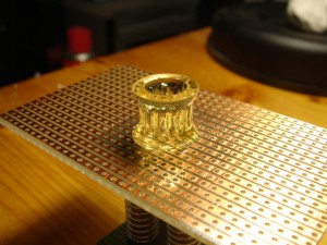
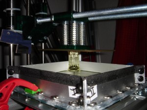
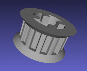
First Successful Print - Belt Pulley
Components
Here I run through the various parts that make up the printer. Future posts will no doubt go into more detail for each one, but this should give a good idea of what I have done so far.
Frame
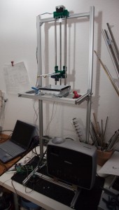
My initial idea was to build the frame with wood but I soon changed my mind for 20mm aluminium profile for the flexibility it would give. Additionally, I picked up various brackets and small steel sheet parts from the local hardware store and my scrap pile to hold things in place. The remaining parts were printed on the Mendel, with the majority of the design coming ScribbleJ's Thingiverse entry, but with a few parts modified to fit the aluminium profiles.
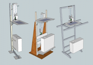
Initial designs in Sketchup
The Frame
I swapped the motor coupling for a thrust bearing design, in order to reduce wobble, and changed the arm that drops into the vat to a modular design using threaded rods and a custom base. The Z axis is so high simply due to the rods I had lying around being that length. The middle sketchup design shows an alternative where the bulk of the Z-axis goes below the vat table, but this introduces more parts and a potential source for more wobble.
Vat
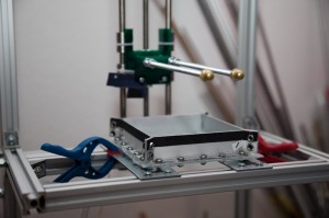
I can already foresee that this component will undergo many revisions. The interaction between the vat floor and the layer of resin being activated by the UV light is critical, and subject to much discussion on the yahoo forum. As I will detail below, already my initial version quickly developed problems and has had to be rebuilt. But for reference, in version 1 I used off cut aluminium extrusions for the walls and 2mm thick perspex (acrylic) for the base. On top of the base, secured between it and the walls, is a PTFE film layer (PDF data sheet). The whole thing was made water-tight with standard transparent silicon caulk.
Vat and Z-axis Lift System
Resin
The key component which, to date, has impeded DIY DLP resin printers due to it's exorbitant cost. However, this is already changing. I bought 1kg of Spot-GP resin from spotamaterials here in Europe for ~€85 (+€35 shipping to Germany). Still way more expensive than materials for FDM printing, but I imagine prices will drop over time as they did with PLA filament.
Projector
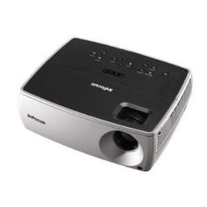
This is perhaps a tricky component to acquire as there are so many options open and one wants to be sure of getting the right one. After several days of hunting on Ebay, local classifieds and even Amazon, I lucked-out and found an InFocus IN2104 on Ebay which I picked up for €170.
InFocus IN2104
The most important feature is that the projector has to be one with DLP technology! LCD projectors filter the necessary UV light and appear simply not to work. The next key properties I looked for were the wattage of the bulb and the native resolution. My initial plan was to get one with 800x600 resolution, but I changed my criteria to a higher resolution for the simple fact that I could imagine soon wanting higher definition in my prints (it affects the X/Y resolution of course) and would be kicking myself if I had to buy another projector after 6 months. The IN2104 has a resolution of 1024x768.
I considered bulb wattage a more important factor than the lumen rating as it seems the lumen values given by various manufacturers varies considerably, and I got the feeling, after reading many reviews, that the lumen value is not very dependable. Saying that, higher lumen is generally better, but also look at the bulb wattage. The InFocus has a 200W bulb. Most projectors I looked up had values around 180W, particularly Acer, and so the exact value will depend on the brand and model. I set myself the hard criteria of type and resolution, and then was a bit more flexible on bulb wattage, price and availability.
Base
The part which the first layer attaches to and, in my case, rises up from the resin. My initial tests were with wood and then perspex because I had no local source of glass pieces, which seems to be the preferred material. These proved unsuccessful and so I tried a couple of other materials I had lying around. It seems that copper PCB board and stripboard work quite well. With the latter allowing the resin to harden within the holes and potentially provide a better grip - but this is only a hypothesis. I shall no doubt replace this in the future revisions, but it provides a cheap starting point.
The board is simply glued to a small 3D printed piece which allows four PCB stand-offs to be attached. These provide the lift over the rim of the vat. The stand-offs are then screwed to another 3D printed part which in turn goes on the vertical Z-axis rods. Over the stand-offs are stiff springs - these allow each corner to be individually adjusted so that the base is parallel with the vat floor.
Base pulling out 1st almost successful print
Whilst using threaded rods for the vertical Z-axis was handy because I had some around, I think these will soon be replaced with an L-bracket design as there is some flex in the rods. The weight of the model is negligible, but the suction force of the part and the vat floor can be considerable and it is therefore a design goal to reduce flex where it is not wanted.
Lens Throw Reducer
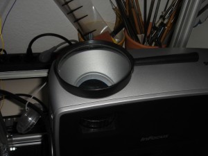
The shortest distance the projector can throw, and be in focus, is approximately 35cm (if I remember correctly). One could possibly open the projector and physically modify the focus mechanism, or lens, in order to reduce the throw (as Mike has done with his B9Creator), but I'm wary of making modifications to the projector itself and so opted to use a cheap magnifying glass to do the job. This choice has obvious disadvantages - optical distortion, inconsistent image placement, etc - but it's cheap and it works fine during the initial phase.
Hi-Tech Lens Throw Reduction System
Resin Delivery
I expected to have to design a resin delivery system - perhaps something as simple as an upside-down bottle with a tube to the vat floor, with the liquid pressure regulating the delivery - and I may still do this. In the meantime the vat holds enough resin to complete my small test prints, and I load the resin via a large syringe.
Host
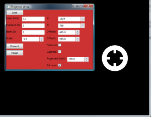
I am using a modified version of Printrun, adding the following features:
- Open the presentation window fullscreen in a second monitor.
- Project a calibration grid
- Display the first layer of the model - useful for displaying the first layer longer than the subsequent layers.
- Accept SVG from Slic3r. (Update: To do this I replaced the SVG module with wxpsvg which has a dependency on pyparsing. Install instructions are on the pyparsing site.)
- Accept a set images (bmp, png, jpg) in a zip file (with suffix .3dlp.zip so it's recognisable but can also be opened in a regular archive program).
Firmware
Sprinter for it's ease of hacking.
Post Cure
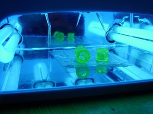
I'm not 100% sure how necessary post-curing is. The parts appear quite stable directly after coming off the base. A bath in isopropyl alcohol may suffice for post-processing, to remove non-cured resin. However, as I had a UV lamp handy I threw the parts under that for a few minutes.
Notes
The following are a few random notes and findings as I got to print #1.
As the resin photo-initiates the reaction is very exothermic. A very quick test with the thermocouple of my multi-meter and a drop of resin on a thin clear plastic sheet in the bright sun produced a temperature change from 23°C to 74°C. This may have been a contributing factor to the demise of my first vat bottom, which I discuss below. 74°C won't burn too much, but it's definitely worth considering - particularly if you get some on your skin and then walk into the sunlight! So be careful! I use latex surgery gloves when testing as the resin tends to get everywhere.
I used a RAMPS board and the related reprap firmware largely because it was lying around. There are a few alternatives as well as the option to roll your own of course. Chris Marion has put together a python based Host which works with the Firmata firmware. It's currently in beta and windows only, but worth considering. Chris's software uses freesteel to produce png slices - this is also worth playing with, although it's not open-source.
Belt Pulley
The initial successful test pieces came out well partly by luck - the model's design is such that even though the exposure times per layer were slightly too long this only reinforced previous overlapping layers directly above. I attempted a more complex print soon after and the exposure times resulted in a solid block of resin where it should have been a mesh of struts within. A standard technique to bring more control over the exposure times is to add a coloured pigment to the resin (between 0.2% and 2% by weight according to Fernando at spotamaterials). Currently I am testing the resin without a dye until I order some. My very unscientific initial tests seemed to show an exposure time of 1 second will harden ~0.1mm of resin - but I have to caveat that there are many factors which can play a part, not least of which is my my poor process. I shall endeavour to produce more reliable figures in the near future.
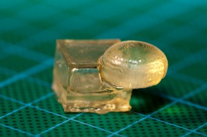
The adhesive properties of the resin are not the only force to contend with. The bottom-up approach has the added problem of a vacuum force - just as with a suction cup. There are several ways to overcome this: brute force (not recommended of course), tilt mechanisms, and slide mechanisms. At the moment the printer simply pulls up, and because the parts are quite small, in comparison with the forces involved, the parts are forcefully pulled vertically off the vat floor. This obviously will have to change, and in fact a subsequent test print nicely highlights this interesting failure:
This should be a cube with a sphere coming out of one edge. The sphere is deformed due to the 'top' of the cube sticking to the vat floor, from vacuum force, for several slices. Either the vat floor, the Z-axis rods, or the something else, flexed sufficiently to allow the part to remain attached, until the force was overcome, and could continue. One way of resolving this would be to adjust the print cycle so that the Z-axis rises several millimetres at the end of an exposure, and then lowers to the next slice height. However this would likely only defer the problem until later, larger prints, where the vacuum force would be greater. I think I will introduce a tilt mechanism as part of the next iteration.
Vat Failure
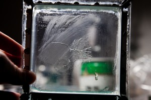
Soon after my initial test prints the perspex vat bottom developed some cracks in the middle, which developed to the point of failure. Prior to this a deformation had appeared at a spot after I had exposed for several seconds (whilst attempting to get the resin to adhere to the base). The autopsy showed that this deformation was mainly in the perspex, and slightly in the PTFE film.
I had done quite a poor job of positioning the bolt holes, and consequently, as I tightened the bolts, slight cracks appears at the holes. Therefore I think it is safe to assume that the entire vat bottom was under some lateral pressure, which may very well have contributed to the overall failure. I also had chosen to use only 2mm thick perspex which could also play a part.
The next iteration has a 4mm thick base and I took much more care to align the bolt holes. I expect a similar failure with this version too, but will hopefully be able to test some more whilst I design iteration 3.
As an aside - as I was writing this post and gathering links and facts I came across an anti-friction dry PTFE lubricant from WD-40 (PDF Data Sheet) which may be worth investigating. It would certainly simplify vat construction! One could simply use a Pyrex dish and spray some PTFE in before each print run. (Of course that's a bit glib - I suspect oven dishes won't have the optical clarity required!)
Resouces
The blogs and forum are certainly worth a read! My thanks to the authors for the information they have shared within.
- http://tech.groups.yahoo.com/group/diy_3d_printing_and_fabrication
- http://3dlprint.com
- http://www.chrismarion.net
- http://3dtisk.blogspot.de
- http://code.google.com/p/lemoncurry/wiki/main
This post is turning out to be quite long, so I shall end here and put the remaining stuff into smaller posts in the near future. Hope the information is useful to someone.
Comments
-
CHICKOTERIA
24-06-2012 01:42
Gary
this is amazing,,,,thanks for posting...i pinned your post on my Pinterest board
Chickoteria " Designers FabLab Manufacturing". I am really interested in how
you progress
cheers
Chickoteria
-
Paul
24-06-2012 14:36
Awesome and evry interesting article !!!
Looking forward for more documentations and results from oyu, im still thinkking of also testing a design or start a project ... but first i will go true oyur whole discription again(later)
keep it up and thanx !!! great work
Paul
-
bitflusher
24-06-2012 14:49
Nice experiments. What is most interesting to me is the use of a stock unmodified dlp beamer. Other experiments remove the colour weel and or modify the lense. I hope to build a DLP beamer somewhere next year.
Good luck on future experiments.
-
sloth3d
26-06-2012 07:20
If I got you right, you are located in Germany as I am. We have nearly the same project status, you are definitely a little ahead :) Where did you source the ptfe-tape? I got mine from the u.s. and delivery took quite long, also it was very expensive. Then I literally lost my tape-sheet ^^ and wanted to look for an alternative. Since there was some success with sylgard I wanted to try that and then found this: http://www.ebay.de/itm/270776478062?ssPageName=STRK:MEWNX:IT&_trksid=p3984.m1439.l2649
I used spota-ht for the test and it turns out the part releases itself from the vat floor if it is covered with this silicone. I have not yet documented this fact in my blog.
-
Gary Hodgson
26-06-2012 08:47
Hi, I bought the PTFE sheet from RS: http://de.rs-online.com/web/p/isolierfilm/5363980
5 sheets of 304x200x0.025MM cost €35.10, which so far seems to work quite well. And if you look at the other insulation films on offer, don't be tempted as I was to try Kapton or Mylar! Kapton blocks the UV completely, and Mylar sticks to the resin a lot more than the PTFE.
I also ordered some PTFE Trockenschmierspray which might also be a good solution - I will write a blog post with the results when it arrives and I have tested it.
Thanks for the link to the silicone - I'll put it on my list of things to try.
Best of luck, I'll be following your progress on your blog! By the way, I post smaller updates on Google Plus, which may be of interest.
Cheers,
Gary
-
sloth3d
26-06-2012 19:35
Hey thx for the response. I already tried ptfe Trockenschmierspray and it cured sort of milky. Maybe you have more luck with yours.
One other thing: I would much appreciate to be able to download the original files you print, the svgs.
I will definitely have a look at your google plus profile.
-
sloth3d
28-06-2012 09:24
Don't use the silocone, it's getting used up and turning a little milky where it is exposed to the light most. This effect is clearly visible after about 100 layers.
-
Sergey Green
29-06-2012 16:53
Hello, Gary Hodgson.
Great job! I also do 3D printer with DLP projector.
?ould you share a modified Printrun?
I think if it is just zip and send the email, it will work. Could you send me this?
Sorry for my english, I'm from Belarus :)
-
Gary Hodgson
29-06-2012 17:30
Hi Sergey,
My version of Printrun is available on github... https://github.com/garyhodgson/Printrun/tree/experimental
If you want to get a zip then this link should work: https://github.com/garyhodgson/Printrun/zipball/experimental
(by the way, I removed your email address from your comment so you don't attract spam.)
Best of luck!
-
Sergey Green
29-06-2012 19:08
Thanks!!!!!
-
Gary Hodgson DLP Resin Printer Lessons Learned « openalia
01-07-2012 21:09
[...] In the never ending quest for higher 3D printing resolution, the hobby community has naturally turned to DLP (digital light processing) in which a liquid polymer is selectively hardened by a projected image. ScribbleJ’s Thingiverse entry is a good first step. Gary Hodgson has written up an excellent analysis of his DLP printer here. [...]
-
Martin Price
03-07-2012 15:17
Gary
A really interesting read and thanks for all the information on resins and projectors. I have just put up an alternative design concept on the reprap forums. Perhaps you could take a look and comment on if it would overcome your stiction issue on the glass.
http://forums.reprap.org/read.php?184,141053,141053#msg-141053
-
joan
16-08-2012 23:54
Hi Gary! I just downloaded your version from github, but I cant open i,there is no pronterface icon. And the zip version is tge standard pronterface download, which is more minimal than your version (there are no pause button, for example).What I can do for download a precompiled version of your printrin hack??? Thanks a lot!!!!!
-
Gary Hodgson
17-08-2012 12:53
Hi Joan, Are you looking at the experimental branch? That's where my modifications are. https://github.com/garyhodgson/Printrun/tree/experimental
-
joan
18-08-2012 13:34
GARY! I'm downloaded the zip of your experimental branch, and there's no pronterface icon inside, I can't open the app (windows).
I need your help!!
THANKS!!!
-
joan
18-08-2012 14:49
Ok, I downloaded and installed all the python stuff, but now I can't instal pyglet. I open a prompt console in windows (bootcamp) in the pyglet directory, I type python setup.py install, but the console tell me is not recognized as internal or externall comand. What I should do??
THNX!!
-
joan
23-08-2012 10:46
Finally is working!!!!!!!!!!!! It was a installation problem of the python stuff, now is solved. The motor moves, and pronterface presents all of my sgv's from slic3r!!!
But the slices are very little, even I model the object in the correct scale (just for fit in the buildlate). Do u know if slic3r scales down the objects when slicing??? or maybe pronterface works in inch, and when I import metric models, they appear way smaller???
Thaanks!!
-
Rob
02-01-2013 02:31
Hi Gary,
I am planning using freesteel for slicing my STL files for a 3D printing project to print with ceramic slurries(resin loaded with ceramic powder). Freesteel has some features I really like e.g. offsetting the contours.
However I am experiencing a problem with it: it seems to mirror the images around the Y-axis?!
(e.g. a bar going from bottom left to upper right comes out on the image file(s) as upper left to bottom right or text/characters appear upside down)
The freesteel site doesn't provide any info on this nor is there any comment.
Looking at other forums it seems you have been using freesteel as well; did you have saw this issue? Am I doing something wrong or??????
Rob
-
Gary Hodgson
02-01-2013 09:41
Hi Rob, I've only used freesteel a few times, and so far all my models have been symmetrical so I have not yet encountered the problem you describe. If I get a chance I will slice a model tonight to see if I can recreate it.
Cheers,
Gary
-
Danny
11-01-2013 23:36
Hi Gary,
I've just discovered your work and I'm impressed!
I've been working on this subject for quite some time and a lot of pitfals you have encountered I've come accross myself. I'm not as far as you are (not for a long way) but I have a question about the electronics. I've build a pic controlled z-ax triggered by the light the projector makes but your method seems to be far more convenient. I looked around for controllers and found a controller called the 4PI from xyz printers caught my eye. (merely because it doesn't seem to need the electronics to drive the stepper motors). What do you think? shall I pursue your way, taking advantage of a well known platform RAMPS or pursue this way? I cant seem to find so much documentation about it....
Any sugestions for the stepper motor? I've seen the NEMA17, do you think its any good?
Thanks for your inspiration!
Danny
-
Gary Hodgson
12-01-2013 01:16
Hi Danny,
Well, the beauty of using something like RAMPS is that it's tried and tested, and there's plenty of firmware options. The downside is that it may be more than you really need (I used it as it was lying here as a spare to my Prusa). If you're wanting to drive more than one motor (e.g. for a tilt mechanism), or utilise the mosfets (for example I used them to make a little experimental heated bath to thin the resin) then a RAMPS (or similar) is a useful thing to have.
If you just want to drive a Z axis then all you really need is a stepper motor, a driver, and an arduino (or if you're au fait with PIC's then perhaps that's an option). Just buying these components would be a bit cheaper than shelling out for a full board, such as the 4PI. You could wire up the stepper driver to the arduino and make sure the pin assignment is correct in the firmware. Go for a arduino clone, and stepsticks instead of pololu and it's be even cheaper.
I use this NEMA 17 from zapp automation, and pololu A4983 drivers from XYZ and I have both an Ardunio Mega (also from XYZ) and an Arduino clone, both of which work fine. Have a look also at reprapworld
As you are no doubt aware, there are plenty of options, and it's definitely worth scouting around to get the best price. Hope that helps - feel free to ping back any further questions.
Cheers,
Gary
-
Danny
12-01-2013 12:45
Hi Gary,
Thanks for your speedy reply!
Athough I've been programming PIC's, I'm inclined to switch to the Arduino world because there are so many people doing all kinds of projects on this platform.
Due to your advice, I'm thinking of making a switch to Arduino (usefull for other projects I might run into the future) Are they programmable in C or another highlevel language?
Thanks for the the link to reprapworld. I saw they are based in Holland (same as me) so the postage will be low.
I'm thinking of the following config (mainly to stay compatible with your software as I probably have a steep learning curve ahead):
1x RAMPS 2560 (ATMEGA 2560)
3 x Stepsticks + 2 heatsinks (1 spare stepstick)
2 x Nema 17
Does this seem okay?
I still don't understand what a RAMP 1.4 does, do I need a board like that? (I used a PIC and a darlington array in combination with a tiny stepper motor)
Thanks for your help!
Danny
-
Gary Hodgson
12-01-2013 17:07
Programming Arduino in C is possible, have a look here: http://www.wikihow.com/Write-Arduino-Software-in-C
Just to clarify: RAMPS is a board that fits onto an Arduino microcontroller board - this is known as a shield. The wiki article has some good information about it. On the reprapworld site, RAMPS 2560 is just the arduino board. You would also have to pick up the actual RAMPS shield too. (I think their site could explain this a bit better really.) Or you could get a kit which comes with the arduino and 4 stepper drivers. (Be warned though, the 1.4 kit has SMD components)
-
Danny
13-01-2013 19:31
Hi Gary,
Thanks for the explanation, I've looked into the processor specs etc. The arduino seem to be a bit more limited in its gadgets, but I think I will go that route anyway since everyone else has (don't want to invent the wheel again anymore, my wheels seem to turn out square a lot :)
I'm ordering the complete set of ramps 1.4 from 3DGadgets (assembled (bad eye site)) and the mototrs from reprapworld and take it from there. I
In the mean time I've tried to experiment with your experimental dist. for windows software but except for loading BMP's from a zip file in the (your) projector option, (looks great though!) I don't seem to be able to let the software slice in the printer Interface.
I get the error:
python: can't open file 'skeinforge/skeinforge_application/skeinforge_utilities/skeinforge_craft.py': [Errno 2] No such file or directory
Do I have to install skeingforge seperately? Is there a windows msi for this? (I'm a bit anxious about installing Python in my dev machine...)
BTW, have you made any additional progress on your DLP printer project?
Cheers,
Danny
-
Gary Hodgson
14-01-2013 11:03
Hi Danny,
You're quite correct in that skeinforge has to be installed in order to be used from Printrun. I actually don't slice from within Printrun myself, instead I use Slic3r to generate the SVG file. If you're not wanting to install python then perhaps it's worth you having a look at this instead. It's written in perl, but it's available as a precompiled package on Windows, Linux & MacOS.
My DLP printer is currently in hibernation as I simply have too many other things going on at the moment. But I will be starting it up again soon (I hope). And I will be sure to post something about it once I do.
Cheers,
Gary
-
Danny
16-01-2013 20:33
Hi Gary,
Got my steppermotors today! Still building on the z-axis mechanics and waiting for the electronics from...China (the site said they would ship from Poland but alas, as long as they get here). The steppermotors have a voltage rate of 3.1V and 2.5 A. Hope this will work with the electronics.
Just an odd question: Can you remind me why everyone is building their 'object' from the top downwards, pulling the object out of the resin and add layers to the bottom of the object ?
Obviously there is the cost aspect of having a hughe vat filled with resin when you want to push it into the resin and cure layers on top of the 'object'.... But is there another consideration?
Cheers,
Danny
-
Gary Hodgson
16-01-2013 21:09
Hey Danny,
I believe several people use the top-down approach. The other disadvantage, other than the cost as you say, is that there is a slight bulge due to surface tension. Some have used a wiper to try and alleviate that.
I actually reconfigured my printer to try top-down as well, and I got more complete prints from it than the bottom-up method, mainly because the problem of the part detaching from the base is eliminated.
Cheers,
Gary
-
Danny
16-01-2013 21:29
Hi Gary,
Just saw your comment, the surface tension I thought of that too, but I thought it would be neglectable because of the same material. But I'm going that route as well because of the hasle people have with the sheet of ....whatever it is...on the bottom of the vat.
(I have some nice ideas, I think)
Do you think the motors 3.1V 2.5A will work with the A4988 Step Stick stepper driver ?
I've tried to contact the resin guy from Barcelona (spot-A), but he doesn't seem to read his mail, did you contact him?
If I bother you to much, just let me know :)
Danny
-
Gary Hodgson
16-01-2013 22:23
No worries, glad to be of help (but if you prefer to use email my address is contact@garyhodgson.com)
I got my resin from spotamaterials, but that was last year and I haven't been in touch with him for a while. Perhaps he's on holiday?
Regarding the steppers: I think they should be ok. Looking at the driver specs I gather they drive up to 2A, and the motor specs almost match the ones I have. However I should note that I am quite a noob when it comes to electronics. Remember to take heed of the warning on the drive spec: "Warning: Connecting or disconnecting a stepper motor while the driver is powered can destroy the driver. (More generally, rewiring anything while it is powered is asking for trouble.)" I did this and destroyed a driver, rather frustrating!
Cheers,
Gary
-
Danny
23-01-2013 17:16
Hi Gary,
I've got a question, What voltage do you put on your board for the stepper motors (mine are 3.5v) As far as I can see the stepper sticks convert the input voltage to 5V. Can I put just 12V on the 5A terminal and leave the 11A unconnected?
I've tested the software with the firmware and it seems ok (with no power or motor connected) but there is no LED feedback to see if a stepper pulse has been given. Is this correct?
(I'm a bit carefull here because of your previous warnings and... as a good friend of mine said: Electronics are made of smoke, don't let it escape!)
Danny
-
Gary Hodgson
23-01-2013 19:50
Hey Danny, If I remember correctly, I has 12v from an ATX power supply going to just the 5A terminal for a while, and I only added another 12v to the 11A terminal because I added a heated bed (this being for my Prusa, not the DLP printer). Considering the board will only be driving a couple or so steppers I think just the 5A will be fine.
And you're correct: there is no LED feedback from the board.
And careful is always a good idea :)
Cheers,
Gary
-
Danny
24-01-2013 17:20
Hi Gary,
Thanks! I got it running (No smoke).
I used an old AT 300W power supply, Connected the green lead (of the motherboard plug) to a black lead (ground) to activate the power supply. Then I used the 12V lead (Yellow, rated at 14A) to the 5A connector.
There is one odd thing though, I used the connection schematic from http://reprap.org/wiki/RAMPS_1.4 and it shows the motor connection as RED-BLUE-GREEN-BLACK, the connector on my stepper is BLUE-RED-GREEN-BLACK. (RED and BLUE are reversed). I havent found out what consequences that might have, but for the time being it seems to work ok. (any idea?) I think this might change the polarity of one coil.
Now I only have to fine tune the two pots on the stepper driver after I connect the z-axis. Then see if I can source the Beamer and the resin and then I can try the whole thing out.
Cheers,
Danny
-
Danny
24-01-2013 17:26
Oh btw: For anyone else going this route: If you haven't connected your real endstop for the Z-Axis, don't forget to shorten the pins marked S and - on the connector marked 'endstops' else your test setup won't work.
-
Gary Hodgson
24-01-2013 20:59
Hey Danny, Great to hear you got it set up! Regarding the stepper wiring, I guess it depends on what make/model they are - there is this page on the wiki which gives some more info about identifying the wire pairs - perhaps that helps? But if it's working then it sounds like you've got the right ones.
Looking forward to seeing the printer take shape!
Cheers,
Gary
-
henrypan
25-01-2013 20:13
Hi Gary,
Have you tested the PTFE TROCKENSCHMIERSPRAY? I am also building a 3d printer in London, I am not sure of buying PTFE sheet or PTFE spary.
Regards,
Henry
-
henrypan
25-01-2013 20:18
Hi sloth3d,
Do you mean Sylgard 184? What material do you use in the end?
By the way , your blog seems not working.
Henry
-
Gary Hodgson
25-01-2013 23:29
Hi Henry, I did try the PTFE spray but with no success sadly. The problem being that it isn't really "trocken" enough, and wiped off after a few exposures.
At this stage I would recommend either trying Sylgard, as others have had success with this, or the PTFE sheet. But I strongly recommend getting as thick a sheet as you can afford. The ones I bought originally do not last very long - all it takes is a slight tear as you take off a part and the base can be ruined. I have since bought some thicker sheet, but not yet found time to test them out.
Best of luck!
Gary
-
henrypan
26-01-2013 01:09
Thank you for your reply, I have ordered PTFE sheet on RS, and will order Sylgard 184 as well to test both of them.
By the way, for the vat material, perspex is the one you tested, what thickness do you recommend? Have you tried glass vat like others, I wonder does perspex block some UV lights?
Henry
-
Gary Hodgson
26-01-2013 09:14
Hi Henry. I'll be interested to hear your results!
Regarding the vat material, I actually switched from Perspex to glass because it seemed the heat from the resin reaction caused stress, and cracks, in the material. So I would recommend getting glass if you can.
Cheers,
Gary
-
Danny
26-01-2013 10:10
Hi Gary,
Someone is offering me a DLP beamer, a HP MP3322 XGA with 200W P-VIP lamp (2400 ansi lumen). Although it costs only 150 euro, If its not going to work it will be wasted.
Any ideas?
Cheers,
Danny
-
Gary Hodgson
26-01-2013 15:03
Looking at the specs it seems very similar to mine. The resolution and bulb wattage match what I have. I paid €170 for mine and consider it a good deal. I would probably go for it myself.
-
henrypan
27-01-2013 00:02
ok. I will inform the result once I get the material and tested,
Thank you for your advice!
Cheers!
Henry
-
Danny
02-02-2013 00:59
Hi Gary,
The buy of the beamer didn't turn out well, broken... So I just have to find another. Found two other ones in one buy. They are only 180 watts (infocus x9, 1280x720), but beggars can't be choosers.
Hope this is a good deal!
Keep you posted,
Danny
-
Danny
04-02-2013 16:40
Hi Gary,
I've got the 2 X9's and they are in good shape.
I'm wondering, since I've read that the best curing seems to be under 400nm, if it would be possible to change the bulb of the beamer with an UV LED.
The LED has of course only a fraction of the energy, but on the other hand, most of the energy of the standard beamer lamp lies in the higher (visible) spectrum (prob most in the infrared area, hence all the heat).
But I don't seem to be able find out how much energy of the standard beamer lies in this spectrum and how much energy one needs for curing.
Any ideas where to find some additional info on this?
Cheers,
Danny
-
Gary Hodgson
04-02-2013 17:06
Hi Danny, Nice work on the X9's. Regarding UV LEDs, The only thing I can say is that when I was looking for them, the ones with the correct wavelength, and useful power, were really expensive. And whether or not such an LED could be installed in the projector I really can't say - I'd have to recommend looking/asking on either the the Yahoo group (http://tech.dir.groups.yahoo.com/group/diy_3d_printing_and_fabrication), or the RepRap forum (http://forums.reprap.org). This wiki might have some info too: http://3dprinter.wikidot.com/dlp-projectors
Cheers,
Gary
-
Danny
08-02-2013 18:57
Hi Gary,
Been busy reading up on the use of the UV light sources. (thanks for the links) Even Ti says the UV spectrum will kill the DMD chip so no go on that front.
In the mean time I have another problem...the resin. I wanted to try out my working setup and order some at Spot A, but I've seen their prices went up and the prices on their site appeared on checkout to be all ex. VAT. Together with the shipping, it turns out to be just too expensive for me.
I now have been polishing up on my chemical skills and have been reading a lot on all the possibilities. But there doesn't seem to be so much posting going on on this subject in the forums anymore. Also I've seen that most of the usefull info about uv blends has disappeared/deleted.
Well, that probably would have been too easy anyway (lol)
Keep you posted and if you have any hints?
Cheers,
Danny
-
Gary Hodgson
08-02-2013 22:59
Hi Danny,
yes, sadly the resin costs can be quite restrictive and I don't think they will come down as quickly as we would like.
From the little research I did the main problem is acquiring the raw materials (suppliers only sell in bulk and to registered companies) and even these raw materials are very expensive. If I remember correctly, when I calculated the costs it came out to be even more expensive than what you could already find online, e.g. at spotamaterials.
Speaking of which, I checked the prices to what I was quoted ~8 months ago and they don't appear to have gone up, but that depends when you last checked. From my interactions with Fernando @ spotamaterials he seems a nice guy who is really trying to make resins available as cheap as he can. Of course I would love for them to be even lower somehow.
Best of luck in your research, I'll look forward to hearing your results.
Cheers,
Gary
-
Danny
29-05-2013 15:53
Hi Gary,
I'm trying to install your printrun version on an XP machine and I get the message pronterface.exe is not a valid Win32 application. On my Vista machine it works fine. Any experience with running it under XP sp2? Is pronterface an 64 bit version? If so, is there any way to get a XP compatible version?
Thanks in advance!
Danny
-
Gary Hodgson
29-05-2013 17:09
Hi Danny,
How comfortable are you with running the idea of installing Python (2.7) and trying to run printrun from source? I might be able to find time to recompile a package for XP, but I can't promise anything. Running from source would be the quickest option for you at the moment.
Cheers,
Gary
-
Danny
29-05-2013 22:02
Hi Gary,
Thanks for the speedy reply. I've got an old XP laptop I want to dedicate as a 3-printer computer, so no problem installing python (although no experience whatsoever...).
I need to get it working to test and fine tune my new resin formulas.
I looked at https://github.com/garyhodgson/Printrun.git , but I've no idea what I need from there. Is there a zip file with all the files and the right directory strucure?
Thanks!
Danny
-
Gary Hodgson
29-05-2013 23:27
Hi Danny,
There's something we could try before you try installing python and all the dependencies. Instead, you could try installing the Windows runtime files that the printrun exectuable needs from here: http://www.microsoft.com/en-us/download/details.aspx?id=5582 Download and run the vcredist_x86.exe file and it should install the required dll files onto your laptop. Then try the printrun executable again - if it still complains then try deleting the folder called "Microsoft.VC90.CRT" which is in te same directory as pronterface.exe.
If that still fails then we can try running from source, Instructions for installing python and the dependencies on windows are here: https://github.com/garyhodgson/Printrun#windows-1 and the source can be downloaded as a zip from here: https://github.com/garyhodgson/Printrun/archive/experimental.zip
Feel free to switch to email as this may need a bit of back and forth to get done - contact@garyhodgson.com
Cheers,
Gary
-
Danny
26-06-2013 12:02
Hi Gary,
I've got the resin working!
It is fast, even on my 180 watt beamer (no modifications) it takes 2 seconds per layer (0,1mm). It is quite sturdy as well, I have drilled some holes and did some grinding and it seems to be quite 'toolable'
I've used the SVG files that come with your version of pronterface. I would love to test the ball sphere and the planetary gears I saw in your pics!
The problem I have is that I don't seem to be able to produce a working svg file. I have used Slic3r to produce the SVG file from a STL file using the option 'Slice to SVG' but whatever I do the file won't 'Present' (show) in the projectlayer display.
Printer Interface says that is has 199 layers found it also detected a layer thickness of 0.1mm and goes through all the layers when I press 'Present' in the ProjectLayer Control but the ProjectLayer Display doesn't show any slides.
Any Idea?
Thanks in advance!
Danny
-
Gary Hodgson
26-06-2013 12:43
Hey Danny, That's great to hear!
If you send me through the STL and SVG files by email I will have a look when I get home.
-
boyu wang
05-08-2013 17:23
A quick suggestion, has anyone tried to use LED monitor or smart phone screen to print?
You can set those right under your prints, because the curing only need certain wavelength. I suspect it would work the same way with higher resolution and easier set up.
-
Gary Hodgson
05-08-2013 19:38
Hi, I actually did try once to use an LCD screen as a filter, with a UV lamp shining through - however I had no success, because the LCD had a coating, or was treated in some way, so it filters out UV. It turns out that that UV light is damaging to LCD displays.
-
boyu wang
06-08-2013 01:51
Make sense polymers cracks under excessive UV rays... I wonder if there is a way to remove the coating. I wonder if anyone makes monitor or display specifically for 3D printer purposes, I don't think it would be too hard to make, but probably hard to do at home.
-
Danny
11-08-2013 18:07
Hi Gary,
It has been some time and I'm working on setting up the distribution, the bulk mixing and the packaging of the resin with my suppliers. Pffffff.. its quite a job! especially with all different suppliers. I hope I will be able to pull it all off.
In the mean time I am trying to establish the shrinking quotient of the resin. I suddenly found out that the projectLayer display seems to make a mistake in the dimensions.
I have calibrated the projectorLayer Display and the grid shows exactly 10x10 mm on screen (or on the projector).
When I show the first slice of a project it shows significantly smaller. In the beginning I didn't notice this because everything was uncalibrated, but now it is a real issue.
When I look into the SVG file created by slic3r it shows for an object of x=20 y=23 z=11 the following: svg width="20" height="23". Loaded in Projectlayer it shows a height of 11 mm so on paper it all seems to be ok.
When I present it, the real (onscreen) dimensions are x=17 and y=20, the measured height of the printed object after printing is ok.
I have tried to compensate by using the scale option in the projector, but that only works (partly) when downscaling, upscaling only seems to work in whole numbers (from 1x to 2x for instance)
I'm sure it isn't a hardware related problem, nor windows related because on diff. machines under diff. versions of windows it makes no difference. Even the windows version versus the Python version acts the same.
Any idea where I am making the mistake here?
Thanks again for your help!
Danny
-
Gary Hodgson
11-08-2013 18:30
Hi Danny,
Only just recently someone else told me of this bug - I hadn't noticed before because it only happens with some models, not all. I am trying to get to the source of the problem and will let you know when I do.
As I was investigating the problem I discovered the scaling issue you also mention - this has been fixed in the latest version, either via github (https://github.com/garyhodgson/Printrun) or via the windows executable (https://dl.dropboxusercontent.com/u/22464622/garyhodgson-Printrun-experimental-dist.zip)
Cheers,
Gary
-
Danny
11-08-2013 21:46
Hi Gary,
thanks, the new version scales much better! Only the calibration with the grid doesn't really work anymore.... Given the grid is 10x10 you now have to gues the width grid because measuring the actual size gives a far off result. Once you got the right x size number, the size of the object seems to be ok! (the one I tested) I haven't installed the Python version yet.....
Best regards,
Danny
-
Gary Hodgson
11-08-2013 22:14
Hi Danny,
Well I finally tracked down the cause of the scaling bug and, as ever, the cause was embarrassingly simple - although very hard to find. I have just updated the windows version (link as above) so please let me know how your testing goes.
Cheers,
Gary
-
Danny
11-08-2013 23:54
Hi Gary,
I hate to break it to you...but the projector isn't working anymore. The projectorlayer display screen opens, but the projectlayer control screen doesn't anymore.
The version I installed earlier this evening does the same now. The old version still works.
I don't think it is a big thing, I think something went wrong during compiling, but it works on your development machine prob. because you have all libraries available. (Thats what happened to me so often)
Thanks for getting into it so soon!
Danny
-
Danny
20-08-2013 22:54
Hi Gary,
I have just aired my website: www.funtodo.net , where I introduce the new affordable 3-d dlp resin to all dlp printing enthusiasts.
I hope to find distributors for all countries to make the resin even more affordable for the end-users by saving on the shipping costs.
Thanks again for all your help!
Danny
-
Boca
25-06-2014 14:08
Hi Gary.
i ordered this PTFE, but i surprised, it is not a self stick version. can U tell me how did U stuck it to the VAT? any tricks? glue? :)
thx.
