Thoughts on Fill Algorithms
Whenever I'm watching a print (because it can be hypnotising after all) I usually become acutely aware of any superfluous aspects of the design and how inefficient the fill patterns can sometimes be. The fact that the model is sliced into layers leads quite naturally to filling each of these layers with a 2D pattern. The line and grid patterns from Skeinforge produce stable, solid objects from as little as 30% infill, and for the most part this is sufficient. I wonder though if we can find a better filling strategy? One that utilises the 3D nature of the model.
If the fill is to provide internal strength to an object and support any internal overhangs (ceilings), but also use minimal material, then I guess the ideal algorithm would analyze the model and identify where best to position struts, columns, butresses and such. Taking into account the printers ability to bridge gaps and so on.
Mockup of model with "ideal" fill of struts, etc."
Even if such an intelligent algorithm is possible it would no doubt be so computationally intensive as to break another constraint we should define: that the fill pattern should be determined in a reasonable amount of time.
This is why the line algorithm works very well - it fits almost any organic or non-organic form, and can be computed relatively quickly. This is also demonstrated by the alternative fill patterns that Alessandro Ranellucci has implemented in Slic3r: hilbertcurve, archimedeanchords and the octagramspiral patterns are marked as "slow" and indeed can take a long time to generate for non-trivial models.
X-end-motor.gcode, Slic3r, Line Algorithm, @32s
X-end-motor.gcode, Slic3r, Hilbertcurve Algorithm, @7m 20s"
As a sidenote, this highlights another observation I have made: that the current delineation between 3D model (usually STL format) and Gcode seems skewed, and some information that should belong in the model (e.g. fill structure) is delegated to the runtime process. I'll hopefully expand on this in another post, but it's worth mentioning here because perhaps our view of what a reasonable computation time is, would change if it is moved back along the workflow to model generation.
So the question: Is there a fill pattern, that provides the same strength and can be computed in the same order of magnitude as the line approach, but which uses less material?
Some Ideas
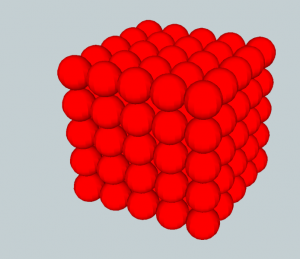
Some initial thoughts involve ways of packing other, simpler, 3D forms within the model, which leads to such things as the sphere packing problem. In this case we would ideally find a solution that has a dense, irregular packing of unequal spheres, where each sphere is the largest possible size for the containing form. Here is where my woeful lack of mathematics causes a real problem. I suspect, but can't be sure, that there is no way of determining such an ideal packing arrangement within the timescale constraints we have set (i.e. minutes, if not quicker).
This also highlights another aspect of the problem: the 3D model we are attempting to fill can be any arbitrary form. If the target model was always a cube, or even always a regular solid, we could potentially pull some tricks (lookup precalculated values perhaps?) in order to use a sphere packing approach. With the prospect of packing non-regular, and potentially very organic, models the problem becomes ever more difficult!
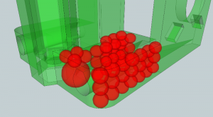
Sphere-Packed Model Example
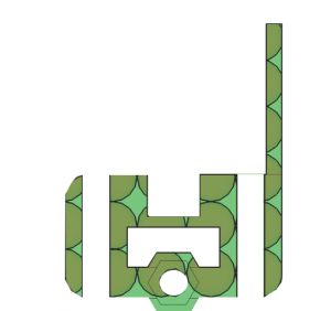
Sphere-Packed Model, Slice Through
Another avenue of investigation is whether an arbitrary model can be divided into simpler shapes? The assumption being that working on several simple solids would be easier and quicker than working on a simple complex shape.
Another idea involves using the vertices of the target model as a basis for generating internal edges, perhaps utilising Delaunay triangulation or something similar, but in three dimensions. This would have the benefit of being tailored for each model, but would it guarantee structural strength? How would such an algorithm work in three dimensions?
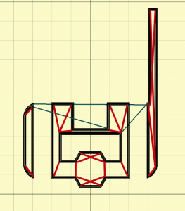
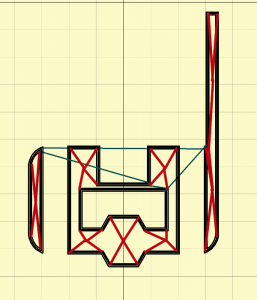
Mockup of slice with example triangulation between nearest vertices
Mockup of slice with example Delaunay triangulation (but not actually correct, only to give an indication)
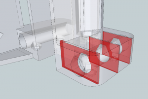
Then something dawned on me: do we have to constrain the fill pattern to the boundaries of the target model? What if we had a pre-defined 3D fill pattern, say a honeycomb, which we intersect with the model to produce the fill pattern?
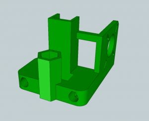
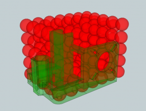
X-end-motor.stl Mendel Part
Sphere Mask
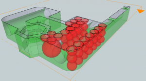
Model Mask Overlay
Slice of Model Packed With Regular Spheres
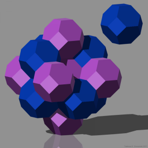
The pattern could potentially derive from a 3D Tessellation.
3D tessellation with truncated octahedron (via Wikipedia)
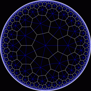
Further browsing online leads to Hyperbolic Planar Tesselations. I have no idea whether something like this could be utilised, but the fractal nature of how the pattern interacts with the boundary could yield ideas for resolving how to give strength to irregular, organic shapes.
Hyperbolic Planar Tesselations (via http://www.plunk.org/~hatch/HyperbolicTesselations)
Mock Print
In order to get a feel for the problem I decided to mock up such a pattern to print. This led to an interesting realisation, that the various tools available will each work with this solution to varying extents. I played with OpenSCAD, Google Sketchup, Skeinforge and Slic3r whilst trying to manually generate an example structure. I found that concept of internal structure in these tools is rather foreign, and I had to hack a bit to get some results. Most 3D modelling tools I have tried concern themselves with solids, the skin of the model, and not the skeleton. Perhaps there exist CAD programs geared towards engineering which use a skeleton + skin paradigm? Perhaps this is also worth investigating further?
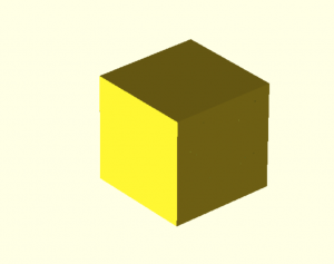
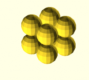
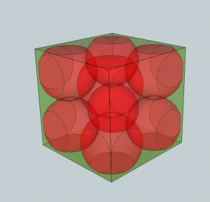
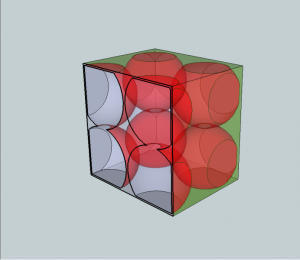
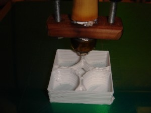
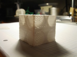
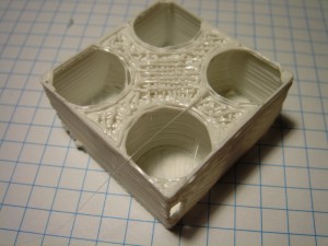
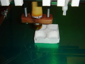
In the end I used OpenSCAD to generate a cube filled with a set of sphere-spaces, and used Skeinforge to slice two models, one with zero infill and one with 30% infill.
Cube Model
Sphere Mask
Cube With Sphere Mask Applied
Cube With Sphere Mask Applied - SectionPlane
It is worth mentioning that I attempted creating a similar structure in Sketchup, but using a real model (Mendel X Motor Mount) and a lattice of spheres (as shown a few paragraphs earlier). Attempting to intersect the spheres with the model caused Sketchup to hang (or rather take an unacceptable amount of time to respond). This perhaps hints at the potential performance problems such a solution may have?
The printed model shows that, for a very basic target shape, the packed sphere approach yields a reasonably rigid object. It is certainly not comparable to a cube filled with 30% line pattern infill, but printing the mock gave me confidence that it is at least worth continuing to research such techniques.
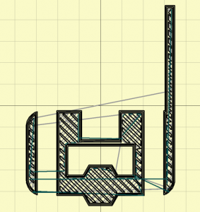
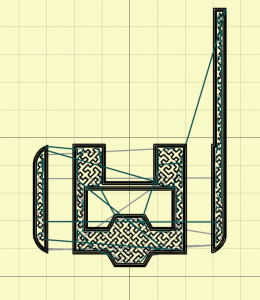
No-Fill Layer 1
No-Fill Complete See-Through
Filled Layer 1
Filled Layer 1
Where Next?
The goal of writing this post was to collect some thoughts on the subject which I could refer people to for discussion. It would be cool if someone more mathematically-minded could comment on the feasibility of such 3D space filling algorithms. Or if others have had similar ideas on the subject at all!
To summarise:
- I think it is worthwhile looking for more efficient fill patterns that take advantage of the 3D nature of the model it is filling.
- The main obstacles are computational intensity and ensuring the resulting model has sufficient strength, regardless of its form.
- It is worth reviewing whether current 3D modelling tools are suitable for defining such things as internal structure. There is potentially an opportunity to develop something interesting here.
I'm going to try and find time to play further and try and throw together perhaps a script to preprocess a model, or perhaps implement a fill algorithm directly. I will also look a bit more at existing tools to see if there is already something out there which allows the definition of internal support structures.
Any feedback would be very welcome!
Comments
-
Dale Dunn
03-01-2012 21:10
An interesting post. I definitely like the idea of a fill pattern that uses less material and by implication takes less time to build. To some extent, users have been addressing this issue by designing structural parts with thin walls rather than simple block shapes. Example
For a show part like Yoda's head, the volume to be filled can be reduced by creating a spherical void approximately at the centroid of the model, but that all needs to be done by hand.
CAD modeling systems don't really deal with whatever the interior of a solid is. The faces are simply a boundary between "inside" and "outside". However, FEA analysis of a solid model involves creating a volumetric mesh similar to the 3D tessellation you mentioned. Algorithms exist for generating meshes of different elements such as cubes of various proportions (generally called "bricks"), tetrahedrons ("tets"), octahedrons, and maybe more. Vertices of each element are called nodes, and they may be useful too.
There are interactive tools used to increase or decrease the mesh density in areas where this is useful to the simulation. (There are algorithmic methods for determining where mesh density should vary from default, but I think they're all dependent on iterations of the FEA solution. Anyhow, it would be useless to us because the density of FEA meshes does not correspond to where we would want mesh density to change.) There are even some meshers that can use elements of different shapes. Surely there is literature available describing at least the less sophisticated forms of these meshers. I know there must be at least one open source mesher, though I don't know its name. I'm sure it's documented somewhere at caelinux.com.
I said all that to say this: The elements of a mesh could determine walls of infill (or support structure), or the interior nodes (nodes not not on a model face) of a tetrahedral mesh could define the centers of spherical voids in the fill. Perhaps some fill elements based on existing FEA mesher elements could be developed to reduce warping as well as reducing the amount of fill.
Perhaps it would even be possible to have the mesher automatically decrease mesh density as some function of distance from the model's faces. This would give strong faces with very little fill of the deep interior.
-
RichRap
03-01-2012 21:59
Great blog post and really nice ideas Gary.
It would be really interesting to test build Speed v Strength of fill and level of infill,I really like the idea of using the vertices of the target model for generating internal edges, this should be fast to print and give strength to the model.
One thing I have always wanted to try is to print a model hollow for say 3-4mm high then place the extruder at regular points in the hollow voids and just purge a set amount of plastic into the void, move the extruder on a regular distance and maybe on a slight regular angle and then purge again, with some experimentation you could get to a level where the purged points just join together and also against the walls of the hollow object,then print a loose mesh over it and build another hollow section, repeat with the same all the way up the object.
It should be fast as you can purge quickly with most hot-ends and strong if the balls are placed well, but may use slightly more plastic?
I did consider making some manual gcode to test the idea of a 'blob-filled-object' but have not tried yet.
If you also had two extruders, you could also have one with a bigger nozzle and low grade plastic for the blob-infill and fine quality plastic on the other for the hollow outline.
-
Gary Hodgson
03-01-2012 22:06
Hi Dale, thanks for the comment! I would never have come across Finite Element Analysis otherwise. From what you describe, and what I can glean from Wikipedia, it sounds like it's worth investigating. As you say, the algorithms used could have an application here - another avenue to explore. The comment about a varying mesher density in relation to the walls coud perhaps produce a pattern similar to the Hyperbolic Planar Tesselation shown above.
What you say about people designing hollow models is spot on. I love the idea behind the Hollow Mini-Mendel for example. As I was pondering alternatives I kept coming back how useful it would be to manually define internal supports to existing model files, i.e. opening an STL file in an editor and saying "ok, a strut should go here, and a joist here", etc. I guess it can be seen as a design technique to create a model which uses the minimum material (I know I always try and cut off unecessary corners and such), but it would be nice to be able to create the (solid) model, and then go into it afterwards adding supports etc. I really think the original designer should at least have the ability to say how the model should be supported, with the next best thing an intelligent algorithm of some sort.
Lots to read and lots to play with!
-
Gary Hodgson
03-01-2012 22:23
Hi Rich, The purge idea would be really interesting to try, and could open up new ways of filling. I'll look forward to reading your writeup if you get around to trying it out! I can imagine solid columns rising within the model, or an algorithm choosing to purge-fill a thin part of the model (e.g. the motor wall in the examples above).
One further consideration I had, about making the internal walls faster to print, is that they could be curved to maximise acceleration. (This is probably the reason I used spheres in my example rather than octohedrons I guess.) I can imagine a series of continuous loops flowing within the model making up the support. One of the challenges I can foresee is how to efficiently connect the support vertices to maximise nozzle speed and reduce retractions and changes in direction. Yet another maths problem! :)
-
Regulus
03-01-2012 22:36
This reminds me of the Rhombic Dodecahedron Infill by Griffin_Nicoll, a similar idea and the same implementation in OpenSCAD to generate a "preview" of what the model might be like, filled in.
I printed a few of those tests, and they were really strong!
I really like your speculation on the tessellation, essentially making the space-filling pattern become a fractal as it gets closer to the edges of the object it fills.
You could generate that by overlapping the pattern with the object, finding locations where the pattern intersects the walls, and subdividing them, then repeat. Large gaps will be filled with whatever size you start with, small or irregular spaces with a sponge of mixed-size shapes down to whatever you specify as maximum resolution.
However, you also have to specify a minimum thickness on the walls, or you will get internal shapes coming up flush with the outer mesh, creating a very thin (but not intersecting) wall, useless as a structural element.
-
Martin Price
04-01-2012 16:42
Gary
Great blog very interesting. I posted on reprap forums, but another thought occured to me. You might have a look at producing the internal structures by raster scanning the head back and forth rather than producing the internal structure by complex paths. It would be a case of just switching the extruder off and on, or using a simple valved nozzle (I think Adrian Bowyer did some work on this) . It would open up the possibility of multiple nozzle heads etc. Doing it this way might throw up some alternative fill patterns you havent yet considered.
By the way if you are struggling with your CAD and need a few test cubes knocked up drop me an email. I have Catia V5 here so should be able to do a few fill patterns quite easily for you to save some time.
-
Gary Hodgson
04-01-2012 19:08
Thanks Martin, when I make some progress I'll get in touch.
I believe this is the valve nozzle that Adrian built that you refer to. Your idea hints at InkJet-type technology, but at a slightly larger scale and more mechanically oriented of course. As you describe , if one had a reservoir of molten material, under pressure, behind a set of "doors" (valve nozzles) would it be possible to squirt the plastic under controlled circumstances I wonder?
Interesting options!
-
Jay Kominek
04-01-2012 19:52
Keep in mind you don't need to find the ideal answer for any of the packing problems you're interested in, just one that is close enough. That is usually quite a bit easier. And in this case, if you can arrange for your imperfections to be ones which cause additional material to be added, then you're not too bad off.
-
Alex
04-01-2012 20:38
Thank you for this writeup. I was working on this line of reasoning myself, mostly headed towards the automated truncated octahedron or shpere packing.
I completely agree with your thoughts on moving some of the fill details to the model. There was an old post syndicated on the reprap blog last spring (http://josefprusa.cz/selectively-making-parts-of-object-stronger-o) that this also made me think of. The idea that increasing surface area in a dimension increases the strength in that dimension (like a tube being more rigid than a rod).
Great post, thank you.
-
Thomix
04-01-2012 20:43
I imagine this would work great with topology optimization software: the way of working I saw was to load an object, mesh it finely and define areas that will bear loads, need a certain thickness or stiffnesses for instance. The software then takes your meshed object and deletes any element that does not contribute to the boundary conditions enough.
I assume this way you can eliminate elements (ie, increase the percentage of infill) without compromising the function of the part.
The only topology optimization software I am aware of is part of HyperX which is commercial (and very expensive) but I can imagine the algorithm isn't that complicated.
-
Gary Hodgson
04-01-2012 22:01
Hi Regulus, Sorry your comment took a while to appear - it went to my spam folder because the link was somehow malformed.
I was searching ages for this link! I knew I had seen something very similar before but my web searches came up empty - I had thought it was a blog post about Skeinforge, and so I got the keywords wrong. In fact it seems I was the first to "like" this Thing! :)
Looking at it again it's obvious that this is the thing that got me thinking about the whole subject in the first place. It must have really stuck in my subconscious because the model I printed is so similar to this one!
I like your idea of breaking down the model into banded zones in order to vary the fill density - I'll certainly keep it in mind when trying to put together the algorithm!
-
dave
05-01-2012 00:55
Hi,
This is funny, I went through the identical exercise.. in cluding the expeeriment to subtract an array of balls from an object to create a sparse structure.. I used solidworks, and had the same result: it simply didn't perform well enough. I also experimented with automated shelling, which works for some objects too.
I ended up concluding exactly what most have said here: that the right place to include the definition of what should be filled and what should not simply should be included in the object definition in the first place. If it deosnt need to be built 100 percent dense, do the modificationa in the model, and then everyone else just prints with 100 percent fill.
It is not sexy, but its right. One of the reasons people do not do this today is that stl files are already horribly inefficient, and creating a complex solid with lots of small internal voids will produce mesh issues.. in my option the biggest problem in the 3d printing chain right now.
Of course if we could all design objects with infill density 'baked in' and then use a decent format like step, the files would be small and slice fast. I have a prototype slicer that will slice step files ( and produce g2 and g3 arcs instead of line segments ) that runs on simple parts like above in about 200 milliseconds. I have been working on honeycomb fill, but in the end even though that's the best fill (can't argue with eevolution) , It is no match for the product designer building it in
-
Ax
09-01-2012 02:43
After reading your post I came to idea that I described in http://axuv.blogspot.com/2012/01/adaptive-infill.html - it should fill small areas with fine fill supporting internal overhangs and strenghtening surfaces, and create stronger ribs which give rigidity to objects with bigger empty internal areas.
-
Gary Hodgson
09-01-2012 08:47
Hi Ax, Thanks for the post, I like the idea, and as you say, it should be reasonable to implement. I think this could be a neat way to handle the heterogeneous shape problem.
I had a similar idea of dividing the model into grids and then using each voxel (I guess that's the right term?) as a basis for determining the internal struts. I was thinking each voxel could be given an attribute describing the force being applied to it (e.g. if it has a filled voxel underneath then the value is lower than one that is hanging over space) and the attribute value being calculated from it's nearest neighbours. Then, when a voxel has an attribute over a certain limit a support voxel is placed underneath, and so on for each layer.
I'm going to collate all the ideas and opinions that have been discussed here, and from the related forum post, into a follow-up post. However, I'll quickly mention an interesting paper which, I believe, achieves similar results mathematically using Functional Representation for the model: "Procedural function-based modelling of volumetric microstructures" (PDF Download) Particularly pages 8, 12 and 17 if you just want to see some images of what it could achieve.
-
Ax
09-01-2012 15:16
Yes, voxel will probably be the right term here. I am not sure how your method would produce printable infill, how you convert your floating support pixels into planes of infill that mesh with each other.
That paper is interesting, but I am not sure how computationally difficult this is.
-
Gary Hodgson
09-01-2012 16:00
You're quite right! As I described it there would be voxels hanging in space. I guess the algorithm would have have a rule that any new support voxel would always have to have another underneath it. (With the algorithm working from the top down). I obviously have to think a bit more about it because this doesn't answer how the infill paths could be derived from such a pattern.
-
Torleif Ceder
11-01-2012 13:56
ProtoSphere: A GPU-Assisted Prototype Guided Sphere Packing Algorithm for Arbitrary Objects [@Youtube]
-
Gary Hodgson
11-01-2012 22:58
Thanks for the link (I added a title so people know where it's leading). The related website is also worth looking at: http://cg.in.tu-clausthal.de/research/protosphere/index.shtml
-
Andy Jackson
07-02-2012 01:11
If the goal is a fractal, just have your outer shell shrunk and supports (at some frequency) from an outer-shell point to it's shrunk point. Then repeat this to the middle. For circles it's great, but irregular shapes would need to redefine the "shrunk" object to not be a simple scale, but a deflation perpendicular to the outer wall so that a shrunk "3d long rectangle" would be a skinnier rectangle and not a scaled-smaller one with diagonal braces.
Although this would only help crush-strength, not shear strength, it could make an easy basis to then make touching-oval or cross bracing between the layer & it's shrunk form that will always perfectly fit.
-
Gary Hodgson
29-02-2012 14:01
For reference in case anyone reads this in the future: Kean Walmsley has written an excellent series of posts addressing many of these ideas. I highly recommend reading the entire series as there are many useful links! http://through-the-interface.typepad.com/through_the_interface/2012/02/sphere-packing-in-autocad-filling-an-arbitrary-solid-using-net.html
-
hairykiwi
03-04-2012 13:52
An interesting discussion and further links, thanks Gary. Have you seen Netfabb's 'Selective Space Structures? (Unfortunately for the DIY community) it's commercial software, priced around €800, however it may provide someone with a little inspiration for an open source solution:
http://www.netfabb.com/structure.php
The links to the lower right side of the above page are worth a look too.
-
Gary Hodgson
03-04-2012 14:17
Thanks for the link! I didn't realise Netfabb had such functionality. It's definitely closely relates to the ideas expressed here.
-
Bruce Layne
20-05-2012 20:15
For computational simplicity AND maximum rigidity with minimal material, I think it'll be hard to avoid a triangular fill. Lots of tensegrity in triangles. Forces applied at a vertex are translated across the matrix via the two adjacent legs. I had linear algebra and could have probably done the Eigenvector analysis back in the 1980s, but I think most people will grok the concept without doing the math. It's intuitive. It's basically the same concept as a space frame.
For each horizontal slice, the algorithm would locate internal corners if available, and draw lines between them. If the resulting triangles are larger than the mesh size to support a ceiling without excessive sagging, each triangle is subdivided into four smaller triangles.
____
\ /\ /
\/_\/
\ /
\/
It's not only computationally efficient when calculating the fill pattern, and efficient in the use of material to achieve a rigid structure, it's also efficient when printing. 3D printers like lines. Some of the other fill patterns require frequent changes in the direction of the print head, so the printer is always in the slow side of the accel/decel curve, thus limiting print speed, and therefore material dispensing rate.
For extruded shapes where each horizontal slice is the same, that would work well, but the concept of a triangulated mesh would need to be extended between layers for more organically curved shapes.
Maybe a good compromise between optimal strength and minimized computational requirements would be a tetrahedral fill pattern at the needed mesh size to support a solid ceiling top layer, that simply intersects with the inner boundary of the outer part surface, as mentioned in the article. I would have linear load paths (rigid) that are distributed throughout the fill matrix (strong and durable).
-
thecraazy
28-06-2012 19:58
While reading the begining of your post I had the same Idea of intersecting the model with a predefined fill pattern... read a little more and VOILA! great minds think alike :P
I think intersecting with a spherical pattern is an excellent Idea that deserves to be seriously looked into. The pattern would be quick to generate and to make the filling more... solid we could make the spheres adjustable in size.
So we could print with a pattern of spheres that are very small for more solidity or larger for quicker prints.
Another thing to look into would be creating arcs (or circles) inside the object, optimized in size and shape so they touch the bottom, top and sides of the objects. No need to print an entire sphere. Basicly similar to your sphere pattern but intersect the bubbles into each other a little so that each bubbles are not entirely separate. (and were the bubbles intersect there is no plastic, you can see trough each bubbles) mm... sorry having a hard time explaining my idea. Hopefully you understand lol.
-
Eki Honkakoski
24-09-2012 16:25
Here is my small contribution to this with two needs (and solution ideas) I have encountered while printing. Some of these ideas are already mentioned above already and some "hollow ball" ideas are quite nice...
This is just more like a report of my (user) findings and needs.
-Fills like line, rectilinear and honeycomb i find useful. Adjustment parameter of fill density has been not enough in my use. To get fill strings (connection points to perimeter) easily with some trial about where I want is my need.
-Fills like Hilbert curve, Archimedian curve and Octagam Spiral I have not found a suitable use yet. Slow speed is not obstacle for me if pattern is otherwise useful.
-I have been missing "zero perimeter printing" - just an infill pattern needed. (like raft or support)
1.
Because we are building in slice by slice most things are in 2D form one after another.
We have already two-three useful methods but placement needs to be structurally improved.
With tesselations of hyperbolic 2-spaces "hyperbolic tilings" we already have:
"Hextille" (honeycomb)
"Quadrrlle" (line or rectilinear)
What we are missing in fills is "deltille" (triangulation)
Also there would be nice to have a mix between triangulation and rectilinear using same and additional "perpendicular" nodes. Like in Pratt Truss (http://en.wikipedia.org/wiki/Truss)
What I´m talking about can be found here:
http://en.wikipedia.org/wiki/List_of_regular_polytopes
There is lines and nodes (places where lines connect) in structural truss theory. Nodes are usually to keep in place by fill lines that takes stresses by stretching and compression. Lines are usually straight if flexing is not needed.
Placement of "nodes" = starting and ending points of fill lines.
Nodes in all corners of perimeter are most important to place correctly - others can move. Nodes on perimeter should be able to place according some parameter like "# of nodes/inch" or"max length between nodes" or "as close to 60° to perimeter as possible"
At themoment a volumetric value of "fill density" makes nodes starting one side to go where ever(?) and missing at least half structurally important places in final part.
This would help my printings and design a great deal.
2. "Backbone" idea
Building inside object an additional "more solid" structure - a backbone - where tesselations - like ribs - are attached to hold thin perimeters -as skin.
This backbone could be also hollow - rectangular or even better oval in section shape to avoid overhangs.
This may be a value in transparent or opaque parts making. Print can be covered with other material (like skin) or be filled with foam or clay etc. to make the final surface in some cases.
This can be partly achieve in 3D drawing placing holes inside the object that slicing understand as place of perimeter, this requires more on designing software… Like hollowing or copying offsetting all faces for smaller object inside and subtracting it from original - placement for center… this has its own disadvantages like uniform thickness when not needed or thinner areas of parts have grater density etc.
Printing with zero perimeter should produce just infill - this I have been missing.
I have wondered it when needed it to make part with a large surface area just with infill but not been able to make before without doing to g-gode (outch!).
Slicer accepts 0 perimeters (minimum) - but likes to make one.... :(
No I stop writing try it harder with "support material"!
Happy printing!
358Eki with Huxley
(thinking already additional machine between multistrusion Mendel or Delta-type construction for high parts)
-
al ket
15-05-2013 15:29
Hi Gary.
reading your paper, I thought of a further approach that might be interesting.
The purpose of filling hllow parts is to obviously to add some strength to the object without consuming too much matter (and time too!).
Evolution faced the same problem with birds bones who must be strong and light weighted at the same time.
Birds bones are hollow but have inner structural lattices that keep them rigid when under constraint.
Bones naturally grow stronger on parts where constraints are stronger.
I suggest the following approach:
- Fill the object with even sized spheres
- Compute the pressure between two adjacent spheres when some kind of constraint (this is the tricky part!) is applied. The constraint could result for example from simulating bending the object on its longer size.
- select the sphere under maximum pressure and replace them by half size spheres (that should resist more)
- remove any sphere having under zero pressure.
- Iterate
The iteration could start with one sphere (the biggest fitting inside the volume).
Variation:
spheres could be replaced with radiuses between their center and the contact point.
-
Gary Hodgson
15-05-2013 18:02
Hi, I think that an approach like this would definitely yield interesting results, and is one of the reasons I started looking at Functional Representation (Frep) as I had seen something slightly similar in the paper “Procedural function-based modelling of volumetric microstructures” (PDF Download) - particularly being able to adjust the properties of holes and struts according to it's proximity to the edge of the model. I had hoped that this could be further developed to have each strut or gap depend on its neighbours - exactly as you describe. So far I implemented a rudimentary playground to experiment with FREP (http://garyhodgson.github.io/frep-csg.js/), and have recreated the structures from the paper, but haven't found the time to develop it further - especially the time to get into the maths behind such algorithms.
Also worth looking at is the protosphere research, which uses an algorithm to pack a model with spheres - it might help out in producing the first iteration, which could then be analysed as you describe. Of course, going from an academic paper to a working example is a long journey :)
-
kloker
11-07-2014 09:49
The packing material algorithms along with the existing tools made this possible. Great work!
